Description
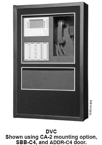
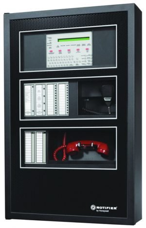
The DVC is the heart of an integrated, full-featured Audio Command Center. The DVC Digital Voice Command combines the capabilities of a powerful digital audio processor, an event-driven audio message generator, and a router. Designed for use with Digital Audio Loop (DAL) devices such as DAA2, DAX and DAA series digital amplifiers, each DVC supports a dedicated audio network with up to eight channels of audio, five channels of firefighter telephone communications, and control and supervision for up to 32 DAL devices. DVCs are available in versions supporting wire, multi-mode fiber, or single-mode fiber media. Larger audio systems incorporating hundreds of amplifiers can be created by networking additional DVC units via NOTI•FIRE•NET™.
The DVC may be networked with ONYX® Series panels via NOTI•FIRE•NET with an NCA-2, or with an NFS2-3030 (running in network monitor mode). A DVC can be connected directly with a single NFS2-640 or NFS2-3030 Fire Alarm Control Panel (FACP) to create a standalone integrated audio solution as well. Refer to the DVC manual for details.
When used as an Audio Command Center with Emergency Paging capability, the optional DVC-KD Keypad Display is required.
NOTE: Unless otherwise noted, the term “DVC” refers to the DVCEM, DVC-EMF, and DVC-EMSF models.
Features
Features
- Listed to UL Standard 864, 9th edition.
- Programmable from NUP port using VeriFire® Tools with:
– DVC-EM: up to 32 minutes of standard quality or 4 minutes of high quality digital audio storage of user-selected/created messages and tones. Supports twisted-pair wire media.
– DVC-EMF: Same as DVC-EM, except supports multimode fiber-optic media.
– DVC-EMSF: Same as DVC-EM, except supports single-mode fiber-optic media.
- Up to 1000 audio sequences.
- Message prioritization.
- Equations support flexible programming for distribution of messages.
- Electrically isolated digital audio ports for direct connection with up to 32 Digital Audio Loop (DAL) devices. Style 4 or 7 configurations supported.
- DCC (Display and Control Center) capabilities when used with optional DVC-KD.
- Firefighters’ Telephone Communications to local FFT riser on DVC, 32 local DAL device FFT risers, and FFT communication to additional command stations via NOTI•FIRE•NET™.
- Local paging microphone option.
- Remote microphone option.
- Broad All-Call functionality when used with DVC-KD (DVC Keyboard Display): All Call, Page Active Evac Areas, Page Active Alert Areas, Page Inactive Areas.
- Auxiliary input for 12 Vp-p analog low-level audio sources. Includes user audio level adjustment feature.
- Auxiliary input accepts external audio sources such as telephone paging or background music. High impedance input accepts 600 ohm, line level, 1.0 VRMS, or 1.41 Vp-p low level audio. Selectable AGC, user control of audio level, and audio supervision are supported.
- Associated NCA-2, or NFS2-3030 (programmed for network monitor mode) supports NOTI•FIRE•NET applications.
- Multiple audio command centers supported via NOTI•FIRE•NET.
- Distribution of one channel of standard-level paging audio on NOTI•FIRE•NET.
- Three standalone, non-network mode options:
– NFS2-3030 (NUP to NUP) digital and analog.
– NFS2-640 (NUP to NUP) analog audio only.
– NFS2-640 with NCA-2 (NUP to NUP to NUP) digital and analog.
- Push-to-talk relay, or logic argument.
- Isolated alarm bus input, to be used for backup activation of alarm messages when normal digital communication is lost.
Installation Options
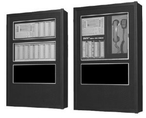
The DVC provides flexible configurations based on one-row or two-row chassis options that mount into size “B”, “C”, or “D” CAB-4 Series cabinets.
The CA-2 supports a DVC, paging microphone, optional FFT telephone, and mounting location for an NCA-2 or NFS2-3030D CPU. The ADDR audio door series can be used when a CA-2 is mounted in the top two rows. The CA-1 supports a DVC and an optional microphone in a single row. For firefighters telephone applications with a CA-1, the CFFT-1 can be mounted in the row below the CA-1.
NOTE: For NFS2-640/DVC applications using DAL devices, an NCA-2 is required to annunciate DAL device events. Refer to the DVC System Audio Product Application Guide (part number M-AG-DVC) for more details on DVC applications).
Product Specifications
- 24 VDC power (TB1): 24 VDC, 1.0 A, non-resettable, power-limited by the source. Recommended wiring: 14 to 18 AWG (2.08 to 0.821 mm2) twisted-pair.
- Digital audio ports, wire media, A and B (TB2, TB3): Maximum distance per segment is 1900 feet (579.12 m) on Belden 5320UJ (18 AWG, TP) FPL cable: 18 AWG (0.821 mm2) twisted-pair, foil-shielded, power-limited. Consult wiring documentation provided in document P/N 52916ADD:C Addendum to DVC and DAA Manuals.
- Digital audio ports, single- and multi-mode fiber-optic RXA, TXA, RXB, and TXB (J100, J101, J102, and J103): ST® style, supervised. Multi-mode fiber-optic cable: 50/125 or 62.5125 micrometers. Single-mode fiber-optic cable: 9/125 micrometers. Attenuation of cabling between two nodes (fiber-optic circuits are point-to-point) must not exceed the following maximum attenuations: 4.2 dB for multi-mode with 50/125 micrometer cable @ 850 nm. 8.0 dB for multi-mode with 62.5/125 micrometer cable @ 850 nm. 5.0 dB for single-mode with 9/125 micrometer cable @ 1300 nm.
- Auxiliary input A (AUX A, TB4): Signal strength from low-level analog audio input: maximum 1.0 VRMS, or 1.41 Vp-p. Optional supervision is selectable through programming. Recommended wiring: 18 AWG (0.821 mm2) twisted-pair; max. 14 AWG (2.08 mm2). Auxiliary input must be in the same room as the DVC.
- Auxiliary input B (AUX B, TB14): Signal strength from low-level analog audio input: 12 Vp-p nominal, 15 Vp-p maximum. Optional supervision is selected through programming. Recommended wiring: 14 to 18 AWG (2.08 to 0.821 mm2) twisted pair.
- Remote microphone interface (TB9): Recommended wiring: 14 to 18 AWG (2.08 to 0.821 mm2) twisted-pair. Power-limited. Maximum distance between remote microphone and DVC: 1000 feet (300 m).
- Push-to-talk interface (TB10): Dry contact. Recommended wiring: 14 to 18 AWG (2.08 to 0.821 mm2) twisted-pair.
- Alarm bus (TB12): Power-limited by source. Recommended wiring: 14 to 18 AWG (2.08 to 0.821 mm2 ) twisted-pair.
- FFT riser (TB13): Power-limited output. Class A (Style Z) or Class B (Style Y) operation. Style Y two-wire connections require a 3.9K ohm, 1/2 watt resistor (P/N K-3.9K). Maximum wiring resistance (including individual telephone zone to last handset) permitted is 50 ohms, 10,000 feet (3048 m) maximum wiring distance at 12 AWG (3.31 mm2) to last handset.
- Optional DVC-AO analog audio output circuits (TB5, TB6, TB7, and TB8): Supervised, power-limited outputs. Signal strength: +12 Vp-p nominal, +15 Vp-p maximum. Recommended wiring: 18 AWG (0.821 mm2 ) twisted-pair; max. 14 AWG (2.08 mm2 ). Maximum impedance: 66 ohms.
Standards and Codes
The Digital Voice Command DVC, DVC-EM, DVC-EMF, and DVC-EMSF comply with the following standards:
- NFPA 72 2002 National Fire Alarm Code.
- Underwriters Laboratories Standard UL 864, 9th edition.
- Underwriters Laboratories of Canada (ULC) ULC-S527-99 Standard of Control Units for Fire Alarm Systems.
Agency Approvals
The listings and approvals below apply to the DVC, DVC-EM, DVC-EMF, and DVC-EMSF Digital Voice Command. In some cases, certain modules may not be listed by certain approval agencies, or listing may be in process. Consult factory for latest listing status.
- UL Listed: file S635.
- ULC Listed: file S635.
The DVC is approved by the following agencies except for use with a DAA2 or DAX Series amplifier, or DS-FM Series fiber conversion module:
- FM Approved.
- CSFM approved: file 7165-0028:224 (NFS2-3030); 7165-0028:243 (NFS2-640).
- FDNY: COA#6026 (NFS2-3030): COA#6025 (NFS2-640).
- City of Chicago approved: High Rise, Class 1, Class 2 (NFS2-3030, NFS2-640, NCA-2).
- City of Denver approved (NFS2-3030).
- PSB Corporation approved (Singapore) (NFS2-3030).


