Deluge Systems are normally used in special hazard installations where water must be applied to an entire area for protection.
Pre-action Systems are used to protect areas where water damage from damaged sprinklers or piping must be avoided.
Deluge Systems are normally used in special hazard installations where water must be applied to an entire area for protection. They use open sprinklers or spray nozzles attached to a piping system connected to a water supply through the deluge valve. The deluge valve is used to control water flow into deluge, pre-action, and special types of fire protection systems in response to a fire. This valve is opened by a fire detection system installed in the same areas. Pre-action Systems are used to protect areas where water damage from damaged sprinklers or piping must be avoided. A pre-alarm of a possible fire allows time for alternate fire extinguishment prior to a sprinkler discharge. They are designed for applications such as refrigerated areas that require maximum protection against inadvertent operation of the sprinkler system.
Applications:
Flammable Liquid Handling
Storage Areas for Valuable Artifacts
Aircraft Hangars
High-Hazard Installations Using Water as Extinguishing Agent
Computer Rooms
Libraries
Archives
Refrigerated Areas
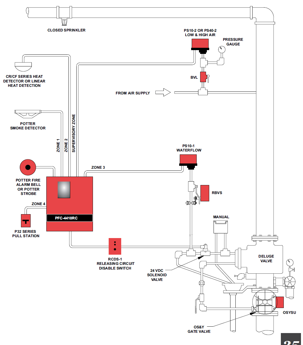
Pre-action Deluge Sprinkler System Diagram
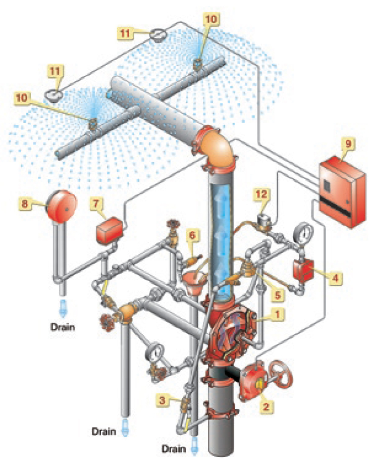
Deluge Systems - Electric Actuation
Deluge fire protection systems are normally used in special hazard installations where an entire area application of water or foam is required for protection. Applications may include flammable liquid handling and storage areas, aircraft hangars, and other high-hazard installations where water is the most effective extinguishing agent. Deluge systems employ open sprinklers or spray nozzles attached to a piping system. The system is connected to a water supply through the deluge valve. This valve is opened by the operation of a fire detection system installed in the same areas as the open sprinklers or nozzles. Deluge systems may be activated by wet or dry pilot sprinklers, or electric detectors. When the deluge valve opens, water flows into the piping system and discharges from all open sprinklers and nozzles. Legend:
Deluge Valve (DV-5)
Isolation Valve
Diaphragm Supply Valve
Manual Control Station
Automatic Shut-off Valve
Automatic Drain Valve
Pressure Switch
Water Motor Gong
Releasing Panel
Spray Nozzle
Smoke/Heat Detector
Solenoid Valve
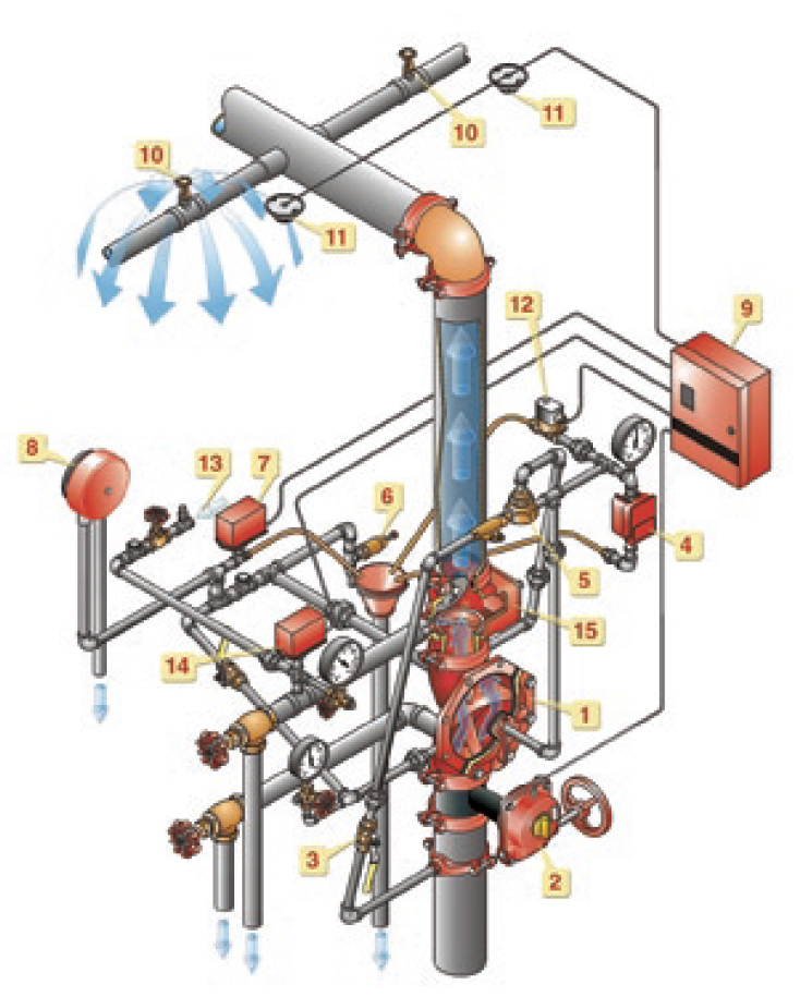
Single Interlock Preaction Systems - Electric/Electric Actuation
Single interlock preaction systems are used to protect areas where there is danger of serious water damage that might result from damaged automatic sprinklers or piping. Typically, such areas include computer rooms, storage areas for valuable artifacts, libraries and archives. Also, preaction systems are effectively used to protect properties where a prealarm of a possible fire condition may allow time for fire extinguishment by alternate suppression means, prior to a sprinkler discharge. In the event the fire cannot otherwise be extinguished, the preaction sprinkler system will then perform as the primary fire protection system.
Single interlock preaction systems employ automatic sprinklers attached to a piping system containing 10 psi (0,7 bar) supervisory pressure, with a supplemental electric fire detection system installed in the same area as the sprinklers. Preaction systems with 10 psi (0,7 bar) supervisory pressure may also be activated by either wet or dry pilot sprinklers instead of electric detectors. Actuation of the fire detection system from a fire opens the deluge valve, allowing water to flow into the sprinkler piping system and to be discharged only from those sprinklers that have been operated by heat over the fire. Loss of supervisory pressure from the system piping as a result of damaged sprinklers or broken piping will activate a trouble alarm to indicate impairment of the system. The deluge valve will not open due to loss of supervisory pressure. Legend:
Deluge Valve (DV-5)
Isolation Valve
Diaphragm Supply Valve
Manual Control Station
Automatic Shut-off Valve
Automatic Drain Valve
Pressure Switch Water
Water Motor Gong
Releasing Panel
Sprinkler
Smoke/Heat Detector
Solenoid Valve
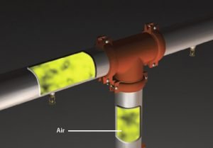
Air Supply Inlet
Pressure Switch (Air)
Check Valve
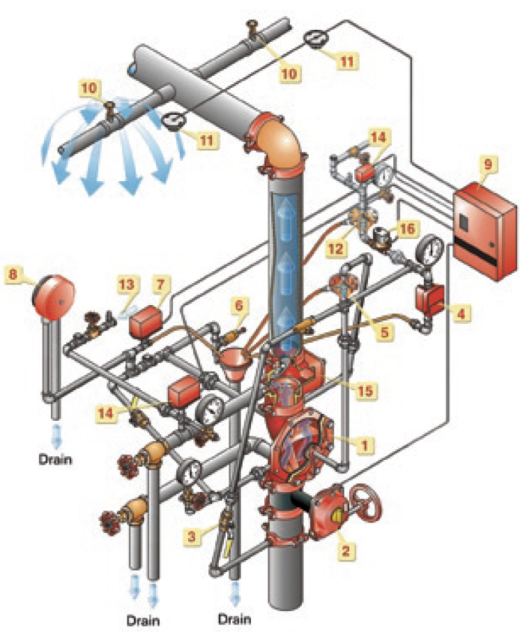
Double Interlock Preaction Systems - Pneumatic/Electric Actuation
Double interlock preaction systems are designed for applications such as refrigerated areas that require the maximum degree of protection against an inadvertent operation that could result in unnecessary flooding of the sprinkler system piping.
The double interlock system consists of a deluge valve and swing check valve with releasing trim featuring both a solenoid valve and a dry pilot actuator in a series configuration. The swing check valve isolates the body of the deluge valve from the system air or nitrogen pressure that holds the dry pilot actuator closed. The solenoid valve remains closed until it is electrically energized by a deluge releasing panel that responds to the operation of a fire detection device.
In order to actuate the double interlock preaction system, two independent events, caused by a fire condition, must occur. The sprinkler system piping must lose air or nitrogen pressure due to the operation of one or more sprinklers, and the deluge releasing panel must energize and open the solenoid valve upon the operation of a fire detection device.
The double interlock system will operate only when both the dry pilot actuator and the solenoid valve are open at the same time. Opening of the dry pilot actuator only (for example: a forklift truck accidentally dislodges a sprinkler) or of the solenoid valve only (for example: accidental operation of an electric manual pull station) will cause an alarm, and will not trip the system or flood the sprinkler system piping.